• This is a political forum that is non-biased/non-partisan and treats every person's position on topics equally. This debate forum is not aligned to any political party. In today's politics, many ideas are split between and even within all the political parties. Often we find ourselves agreeing on one platform but some topics break our mold. We are here to discuss them in a civil political debate. If this is your first visit to our political forums, be sure to check out the RULES. Registering for debate politics is necessary before posting. Register today to participate - it's free!

WTC Core Details[W:183]

Re: WTC Core Details

Please don't conflate my views with Tony's. That's unfair. For a start I don't think he would get into a week long debate with you about round bar Vs angle.
It's not just "round bar vs. angle" gerrycan.

I have brought up numerous mistakes you have made and you either ignore them or try and quickly move on to other things. Until you address those issues and admit your mistakes, this debate is fruitless. So I will start with the first mistake you've made. You posted a picture and circled in green what you thought was a damper.
ang rb HL2.webp

You then further supported that belief with the following two drawings which you added a green circle to show the location and piece you thought matched the one you circled above.
gams angle.webp

rndang comp.webp

You got this COMPLETELY wrong as I had proven, but you ignored it.

What you circled in green here...
ang rb HL2.webp

Is NOT, repeat NOT a damper. It is the lower truss chord made up of angles that sandwich the round bar that makes up the "web diagonals". The photo I edited below shows where the damper SHOULD be. It is where the yellow paragraph is, below the diagonal round bar I circled in red.
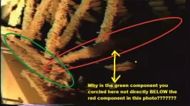
ang rb HL2.webp

You need to start admitting and correcting your mistakes before we move on.
 
Re: WTC Core Details

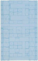
More proof that your 1964 publication cannot be trusted as accurate. Here is a screenshot of the core from the 1964 publication for floors 9 through 16.
1964core.webp

Here is a screenshot of the core from the stamped architectural for floors 9 through 16.
archcore.webp

Very different. This is just more evidence that the 1964 publication used early design drawings and cannot be used for accurate representation.
 
Re: WTC Core Details

Or why did the 1964 publication represent the perimeter column assemblies as covering two floors...
1964perimeter.webp

...and not three floors like what was actually there?
pict3.webp
 
Re: WTC Core Details

In essence gerrycan, you trying to use the 1964 publications as reference for what was actually in the towers and the basis for trying to prove people wrong is laughable. Obviously you didn't do your research on this subject which is why you keep making the mistakes you have.

You think you found a "gotcha" in regards to NIST using the wrong trusses, but are using truss drawings that are not accurate. One has to wonder why you are using drawings from a 1964 publication instead of the actual construction drawings. That's why I asked you to show me the title block way back when. That's when you told everyone the drawings of the trusses came from a "booklet".

There looks to be more detail here, for the long span truss connection at the core. I think your one above isn't a long span truss detail, which is the type at the n face that we are discussing.
View attachment 67228534

Ehhhh ?

I was pointing out that you were posting a short span core end connection detail for the floor truss instead of a long span one. They're different.

This is the short span one here. Compare it to the long span one above, and then your diagram that you added the shear stud bit to.
View attachment 67228536
 
Re: WTC Core Details

The floor truss detail is from the mid 60s booklet I mentioned. I found the link for it.... Contemporary Steel Design Vol.1 No.4 - 911Encyclopedia

It's probably worth having an entirely seperate discussion on.

This is detail "x" which is the knuckle that is red on your pic. Same page as the truss detail.

View attachment 67228543
Just more of your inane garbage. You say above that "Detail X" shows the knuckle (pointed at with the #4 bar callout) and that the knuckle circled in the photo below is one in the same.
vlc 2011-08-19 14-18-36-50.webp

Did you even read the text below "Detail X"? No, you didn't. Here is what it says.
Shear transfer is made by means of s SINGLE No. 4 continue bar anchored at each point of the truss and CENTERED on the 4 5/8 inch floor slab

Let's look at a couple of your mistakes:
1. "Detail X" doesn't show the knuckles (BTW, there are two of them, not one). It shows #4 continuous rebar that was supposed to run through the middle of the 4 5/8" concrete floor horizontally. It never dipped below the surface of the decking.
2. #4 rebar has a 1/2" nominal diameter. The bar used for the truss web diagonals AND which came up through the floor to form the knuckles, was 1.09" in diameter.

You thought the #4 bar in the 1964 drawing ("Detail X") and the 1.09" bar were the same.

How embarrassing.
 
Re: WTC Core Details

The problem here is that you want to leapfrog over a load of relevant data and "cut to the chase". That's not happening.

The thread is about the details of how the floor truss system was connected to the perimeter core column structure by massive shear plates and loads of shear studs. These are not insignificant details that you can hand wave away with generalities.
Here's a typical shear plate showing how the slab extended right into the core structure.
View attachment 67228411
Then you try and pass of a shear plate detail as the TYPICAL type of shear plate used on the floors involved in the impact.

You got that wrong. The detail above shows CORE BOX COLUMNS on either side of the shear plate. Problem is, the columns on the floors in question weren't box columns. They were IBeams (WF shapes).

Try presenting drawings that are relevant to the area in question.
 
Re: WTC Core Details

I am saying that NIST's scenario is an impossibility. The sagging trusses wouldn't have the purchase required on the spandrels (which would also distribute the lateral pull)

On the wider issue, let's just agree to disagree rather than go in circles debating generalities vs detail. :duel
Please explain this garbage would you? How does the "core dropping" increase the "trusses purchase on the spandrels" more than "sagging trusses".
 
Re: WTC Core Details

Moderator's Warning:
The topic is not about each other. Making personal comments to or towards other posters, needs to stop.
 
Re: WTC Core Details

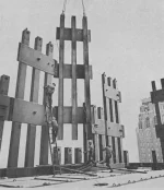
i would just like to add that my original point about round bar was about round bar above the floor pan height apart from the rebar. I have confirmed that now.
It's right around the perimeter of the slab and also between some floor panels using the knuckles to pass through and the welded stand offs to remain at height. There are major amounts of shear studs both at the perimeter column and at the bridging shear plates where the slab enteres the core area of the tower and the truss seats at the core perimeter have also been identified.

Whether someone wants to claim an element on a truss is this or that on a sketch is neither here nor there when all I need to do is to go look at footage of the trusses themselves to see what they are. My original point about rebar on the slab was made and has been vaildated. You can see it here.
96e50afc05e2ba66591a078da841d8ab.webp

It also extended around the perimeter, you can see the cluster of it here. Note how large a diameter it is compared to the welded wire rebar, and also the shear studs following the strap anchor fixing.

4006369579_d162e1b497_b.webp
 
Re: WTC Core Details

i would just like to add that my original point about round bar was about round bar above the floor pan height apart from the rebar. I have confirmed that now.
You have confirmed nothing. You keep exchanging the terms "round bar" and "rebar" like they are the same thing. Do you know the difference? So what "round bar" are you talking about that was APART from the rebar? What has been shown so far to exist is:

1. #4 rebar, 1/2" diameter rods
2. Steel welded mesh, used within the poured concrete to help reinforce it, laid above the decking and having the concrete poured onto it
3. Round bar, 1.09" diameter, used in the floor trusses, sandwiched between the angles that made of both the upper and lower chords, and also formed the knuckles seen above the decking

Again, what additional "round bar", apart from the #4 rebar, are you talking about that was used to help reinforce the concrete?
 
Re: WTC Core Details

bridging shear plates where the slab enteres the core area
You have not showed this either. You used a shear plate drawing that was installed on floors with CORE BOX COLUMNS. The floors within the impact area being discussed in this thread did NOT have CORE BOX COLUMNS. They were IBeams (WF). You used the incorrect drawing for your example. You need to find the correct one and then we'll talk.

Whether someone wants to claim an element on a truss is this or that on a sketch is neither here nor there when all I need to do is to go look at footage of the trusses themselves to see what they are.
Again, you used drawings from 1964 (although now you call them "sketches" to try and downplay the amount of significance you thought they played in your claims) to support your claims and come to find out that those drawings were NOT what was actually installed.

My original point about rebar on the slab was made and has been vaildated. You can see it here.
View attachment 67229243

It also extended around the perimeter, you can see the cluster of it here. Note how large a diameter it is compared to the welded wire rebar, and also the shear studs following the strap anchor fixing.

View attachment 67229244
You have validated nothing because you keep mixing up structural components and can't seem to get the terms correct. How can someone validate anything let alone make a point when you don't understand the very basics.
 
Re: WTC Core Details

i would just like to add that my original point
Why'd you skip over all the mistakes I brought up gerrycan? I thought you said you would admit mistakes when you were shown to have made them? How can this discussion continue when you don't accept being corrected? Your claims are invalid because they are based on incorrect understandings and assumptions. Anyone can look through this thread and see that. Why should anyone take your claims seriously when you have made so many mistakes?
 
Re: WTC Core Details

So do you now agree that the publication corresponds to what can be seen in the construction footage as far as the connection at the core goes?
You tell me gerrycan. After all the proof I have just presented regarding your 1964 publication and how inaccurate it is, what do YOU think?

;)
 
Re: WTC Core Details

In case sanyone is wondering - the round bar can be seen in this image. Pile of it on the left just by the strap anchore near the perimeter.
View attachment 67228603
Note the knuckles on the floor pan are clear of rebar in the direction that the round bar ran when installed.
Proof that you keep mixing terms up as this discussion moves along, making it difficult to understand your points. The components you refer to in the photo above are not ROUND BAR. They are #4 REBAR.

Round bar:
4486151-21.webp

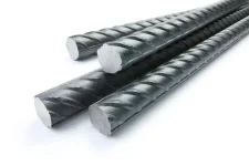
Rebar:
0004770_rebar-domestic.webp

Wire mesh used to reinforce concrete:
Hot-dipped-Galvanized-Concrete-Reinforcing-Wall-Steel.png_640x640.webp
 
Re: WTC Core Details

Proof that you keep mixing terms up as this discussion moves along, making it difficult to understand your points. The components you refer to in the photo above are not ROUND BAR. They are #4 REBAR.

Round bar:
View attachment 67229262

Rebar:
View attachment 67229264

Wire mesh used to reinforce concrete:
View attachment 67229265

Round bar that I mentioned many times, was used both above and below the floor pan level.

The towers used #4 and #5 round bar. This is an entirely different thing to the welded wire mesh rebar, of which they used 2 types.

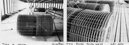
Here is a pic of the 2 types of welded wire rebar they used in the towers.
WWF mesh.webp

There is round bar used to make the trusse diagonals - usually 1.09", but sometimes 1.14", which is what you conflated with the #4, #3 AND #5 round bar that is used to add additinal reimforcement throughout the towers. I mentioned the round bar in the context of providing additional reinforcement between the office floor area and the core floor area.

The only person that disagrees with this is you, and that is because you failed to make that distinction between rebar, round bar and it's use throughout. Fact is that mainly #3 and #4 round bar was used to reinforce the floor slab in particular, at the floor transition areas.
 
Re: WTC Core Details

Round bar that I mentioned many times, was used both above and below the floor pan level.

The towers used #4 and #5 round bar. This is an entirely different thing to the welded wire mesh rebar, of which they used 2 types.

Here is a pic of the 2 types of welded wire rebar they used in the towers.
View attachment 67229296

There is round bar used to make the trusse diagonals - usually 1.09", but sometimes 1.14", which is what you conflated with the #4, #3 AND #5 round bar that is used to add additinal reimforcement throughout the towers. I mentioned the round bar in the context of providing additional reinforcement between the office floor area and the core floor area.

The only person that disagrees with this is you, and that is because you failed to make that distinction between rebar, round bar and it's use throughout. Fact is that mainly #3 and #4 round bar was used to reinforce the floor slab in particular, at the floor transition areas.
Oh really?

Tell me gerrycan, what is the pile to the left in the photo below. Is it round bar or rebar?
View attachment 67228603
 
Re: WTC Core Details

Oh really?

Tell me gerrycan, what is the pile to the left in the photo below. Is it round bar or rebar?
View attachment 67228603

For goodness sake Gamolon. THAT IS FLAT BAR - Used to make the strap anchors, and then used further to be welded over them.
 
Re: WTC Core Details

For goodness sake Gamolon. THAT IS FLAT BAR - Used to make the strap anchors, and then used further to be welded over them.
Just one last reason why I not wasting my time with you and why nobody should take you seriously. Below you said it was round bar. Now it's flat bar. Good grief...
In case sanyone is wondering - the round bar can be seen in this image. Pile of it on the left just by the strap anchore near the perimeter.
View attachment 67228603
Note the knuckles on the floor pan are clear of rebar in the direction that the round bar ran when installed.
 
Re: WTC Core Details

Just one last reason why I not wasting my time with you and why nobody should take you seriously. Below you said it was round bar. Now it's flat bar. Good grief...

The photo's are such poor quality it is difficult to tell what exactly they are. The lack of producing the actual engineering blueprints (copy) and relying on a 1964 book pretty much confirms that the OP question has been answered. No NIST did not get the modeling wrong.
 
Re: WTC Core Details

No NIST did not get the modeling wrong.

NIST got most of their modeling wrong, mike. How can you say something so patently false having seen NIST's totally phony computer simulation for WTC 7? It doesn't come anywhere remotely close to reality.

Also, the lies about the failure of the floor systems.

Transcript : Kevin Ryan : On Why NIST's 9/11 WTC Reports are False and Unscientific

Unfortunately for that theory in August of 2004, just before I wrote to the Government agency, my company had done testing that disproved that Pancake Theory. They built models of exact replicas of the floor assemblies from the WTC Towers; put them in the furnaces and did testing, stripping off all of the fire-proofing for the most part (basically no fire-proofing); they loaded the floors with twice the load known to have existed in the WTC Towers; they raised the temperatures well beyond what would have been seen in the WTC Towers; and yet still the floors did not fail to hold their load.

https://themindrenewed.com/transcripts/536-int-059t
 
Re: WTC Core Details

NIST got most of their modeling wrong, mike. How can you say something so patently false having seen NIST's totally phony computer simulation for WTC 7? It doesn't come anywhere remotely close to reality.

Also, the lies about the failure of the floor systems.

Kevin Ryan , really? Might as well ask Jeff Prager or Gage.

Basically you provided a link to an interview in some off podcast. Which really means you have nothing , zero evidence.
 
Re: WTC Core Details

The photo's are such poor quality it is difficult to tell what exactly they are. The lack of producing the actual engineering blueprints (copy) and relying on a 1964 book pretty much confirms that the OP question has been answered. No NIST did not get the modeling wrong.

I wouldn't be too sure on what can or can't be told from these pics, or that NIST got this correct.

Here's a pic with the elements colour coded to match the diagram below them - it's actually a very telling picture when you look at it closely, and very relevant to the thread. it's either NE looking S, or SW looking N from the corner.

NW lk Sth TA.webp

Face with 20s taken to be North face.....

mark elements.webp

So this pic is AS IF you are at the NE corner of WTC1 looking South (remembering the face with the 20s in the diagram is taken to be North)
 
Re: WTC Core Details

I wouldn't be too sure on what can or can't be told from these pics, or that NIST got this correct.

Here's a pic with the elements colour coded to match the diagram below them - it's actually a very telling picture when you look at it closely, and very relevant to the thread. it's either NE looking S, or SW looking N from the corner.

View attachment 67229443

Face with 20s taken to be North face.....

View attachment 67229444

So this pic is AS IF you are at the NE corner of WTC1 looking South (remembering the face with the 20s in the diagram is taken to be North)

Nice bounce from one photo to another. I was referring to the photo you posted in your post 116. I will be more specific next time.
 
Re: WTC Core Details

Nice bounce from one photo to another. I was referring to the photo you posted in your post 116. I will be more specific next time.

So there's no way whatsoever you or Gamolon could possibly see this kind of floor truss arrangement in the towers ?
ends mirrored.webp
 
Re: WTC Core Details

So there's no way whatsoever you or Gamolon could possibly see this kind of floor truss arrangement in the towers ?
View attachment 67229445

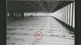
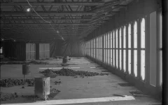
The above photo is not the photo I was commenting on. The B/W photo below is the photo from your post 116. Interesting how you shift things to try and make a point.

WTCrebarfloorsetup.webp
 
Back
Top Bottom