• This is a political forum that is non-biased/non-partisan and treats every person's position on topics equally. This debate forum is not aligned to any political party. In today's politics, many ideas are split between and even within all the political parties. Often we find ourselves agreeing on one platform but some topics break our mold. We are here to discuss them in a civil political debate. If this is your first visit to our political forums, be sure to check out the RULES. Registering for debate politics is necessary before posting. Register today to participate - it's free!

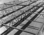
NIST North Tower ANSYS model -- floor trusses

No, you just can't read drawings which is why you want to "move on" so quickly now.

Okay - let's definately NOT move on - let's be very clear and accurate about what that piece you THINK is a "T piece" actually is.

You should really have just moved on.. BIAB
 
Okay - let's definately NOT move on - let's be very clear and accurate about what that piece you THINK is a "T piece" actually is.

You should really have just moved on.. BIAB

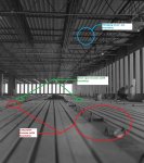
long span core conn.jpg
red box = "T" piece
green box = "L" (angle piece)
 
transverse open webs.jpg

The above shows 2 sets of trusses, both of which form knuckles above the floor pan.
On the long span sides (N and S) the knuckles holes align at 90 degrees to core to perimeter direction
On short span sides the knuckles align in the same direction as the long span sides ie - N to S - NOT from core to perimeter.

These short span knuckles are formed by the transverse trusses rather than the ones running from perimeter to core. You can tell this by the direction of travel of the truss that forms the knuckle being at 90 degrees to the hole alignment.

Does that help at all ?

ADD I don't think I am putting that very well - would a diagram help ?

I shouldn't have mixed "knuckles" and "knuckle holes" in the terminology - if it confuses, then that's my fault.

ADD - note the centre line of the panel.
 
Last edited:
Here's a better pic of a truss from the flooring contractor themselves. There's a whole pdf from them. I could probably link you to it...
image from WTC-Granco Steel-6.jpg
 
What are they then gerrycan?

Hang on, I will draw them onto an illustration for you if I have to and add them here ok

They're the same piece of round steel that forms an open web truss run.

Do I need to go do a drawing ?

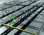
ADD - okay, if the yellow line was where the core was - this is where your red and green bits would be....
transverse open webs.jpg
 
Last edited:
This from the guy who accused me of not being able to read drawings ????
:lamo
Is the section within the red box of the picture below...
image from WTC-Granco Steel-6.jpg

...the same as what is shown in the red box in the detail below?
halfdetail.jpg

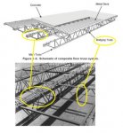
Aren't both pieces the "bridging" mentioned?
 
respond to the first bit first. I think I posted it as you asked that question. I don't want things getting confused - I want to be clear as day, considering you just said that I couldn't read drawings...

ADD - this is actually a good thing, because it illustrates the transverse nature of the corners so well .
 
Hang on, I will draw them onto an illustration for you if I have to and add them here ok

They're the same piece of round steel that forms an open web truss run.

Do I need to go do a drawing ?

ADD - okay, if the yellow line was where the core was - this is where your red and green bits would be....
View attachment 67228641
So you're saying the above picture's red line is what is in the red box in the drawing below and that the green line in your picture is what is in the green box below?
long span core conn.jpg
 
Is the section within the red box of the picture below...
View attachment 67228640

...the same as what is shown in the red box in the detail below?
View attachment 67228643

Aren't both pieces the "bridging" mentioned?

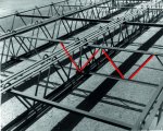
here is where your red bit is - You can tell that this is a long span truss in my pic because they DO NOT form the knuckle - at the corners, things would change slightly, which is what is illustrated in the drawing that you read totally wrongly before saying that I could not read drawings.

Who can't read drawings ?

gams red bits.jpg


ADD to be clear - I mean "your red bit" in the pdf page i gave you from the contactor, not the 60s booklet.
 
I think Gamelon "moved on"..... :lamo
No gerrycan. Unlike you, I have a life outside of debating you on these forums.

Don’t worry. I’ll respond when I get the time.
 
here is where your red bit is - You can tell that this is a long span truss in my pic because they DO NOT form the knuckle - at the corners, things would change slightly, which is what is illustrated in the drawing that you read totally wrongly before saying that I could not read drawings.

Who can't read drawings ?

View attachment 67228646
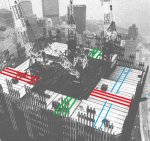
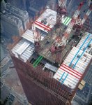
Oh boy... Are you just wrong. You think the LONG SPAN TRUSSES are the ones WITHOUT the knuckle in the photo above? Let's go over this shall we? I'll use two marked up photos to help you out.
new-truss-image-4.jpg

WTCdesign.jpg

Now focus.
The red lines in my above two photos represent the long span trusses.
The green lines represent the short span trusses.
The blue lines represent the "bridging truss".

So what you marked with red lines and declared as long span trusses because of the lack of knuckles is WRONG. That is the "bridging truss" (marked as blue lines in my two photos above).

Below is another photo I marked up to help you.
4061836605_80dd6d7663_b_d.jpg

Even more help. Match up this diagram:
Wtc_floor_truss_system.jpg

With this photo:
Figure-E-2-Mock-up-of-office-floor-framing-system-Photograph-from-about-1967-provided-b.ppm (2).jpg

Edit: Both long and short span trusses had knuckles. The "bridging truss" did not.
 
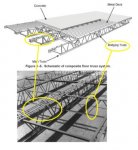
Maybe this will help you further for matching components:
trusscomponents.jpg
 
Oh boy... Are you just wrong. You think the LONG SPAN TRUSSES are the ones WITHOUT the knuckle in the photo above? Let's go over this shall we? I'll use two marked up photos to help you ou.

No.

Long span trusses tpically have knuckles that are formed by the open webs that are going from core to perimeter.
The short span trusses (in the main but not all) have knuckles that are formed by way of the open webs that are running at 90 degrees to the core - perimeter direction.

You totally miaunderstood what was being said AGAIN. I'm not taking hours to explain it to you. Go and reread what is being said.

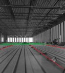
LOOK at the knuckles in the foreground of his picture - they are formed by the steel in the floor truss belowe that is running at 90 degrees to the core perimeter direction. They are short span trusses

4061836605_80ddxxd7663_b.jpg

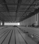
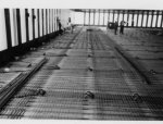
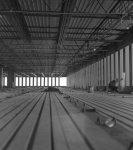
Look at the knuckles in the pic below. They are formed by the steel running in the perimeter -> core direction - they are long span.

WTCrebarfloorsetup.jpg

THAT is what was being said to you.

Understand it before you respond next time. You're making a fool of yourself.
 
Maybe this will help you further for matching components:
View attachment 67228672

You really just don't understand what's being said to you, or you're playing dumb to try and save face.

Which is it ?
Relate the pic above to the short span knuckle one in my first pic please.

I'll wait.
 
No.

Long span trusses tpically have knuckles that are formed by the open webs that are going from core to perimeter.
The short span trusses (in the main but not all) have knuckles that are formed by way of the open webs that are running at 90 degrees to the core - perimeter direction.
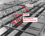
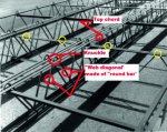
The knuckles are formed by the "round bar" that makes up the "web diagonals" that comes up through the angles that make up the top chord.
knucklediagonal.jpg
 
He STILL doesn't get what's being said.

Read my post then respond.
 
LOOK at the knuckles in the foreground of his picture - they are formed by the steel in the floor truss belowe that is running at 90 degrees to the core perimeter direction. They are short span trusses

View attachment 67228673
No gerrycan. Those are NOT short span trusses in the foreground.

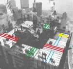
Look at the photo below. I added a yellow arrow to the upper right which indicates what direction the photographer was facing when the first picture was taken. The photographer is STANDING on the long span trusses. How do we know? Because the long span trusses , at each end of the core ran into the SIDES of the short span trusses. That is exactly what we see in the first photo above.
picturedirection.jpg

The red lines below are the long span trusses. The green lines are the short span. Notice how the long span trusses (red lines) run into the side of the short span trusses (green lines). This also corroborates with my photo with the yellow arrow above.
floorphoto.jpg
 
The knuckles are formed by the "round bar" that makes up the "web diagonals" that comes up through the angles that make up the top chord.
View attachment 67228675

The ones in yellow in the pic above would form the knuckles in the foreground in the pic below. This isn't that difficult a concept.......
4061836605_80ddxxd7663_b.jpg

Can't wait to explain the differential floor shortening to you. That'll be an interesting year.....

ADD - Here's the ones in yellow marked for you I thought I'd inserted it
yellow studs.jpg
 
The ones in yellow in the pic above would form the knuckles in the foreground in the pic below. This isn't that difficult a concept.......
View attachment 67228678

Can't wait to explain the differential floor shortening to you. That'll be an interesting year.....

ADD - Here's the ones in yellow marked for you I thought I'd inserted it
View attachment 67228679
That's the "bridging truss"!!!!! That is neither a long span OR short span truss!!!! The "bridging truss" ran perpendicular to the long/short span trusses!!!! See diagram below!!!! The knuckles of the "bridging truss" did not come up through the decking. The knuckles you see in all the photos are from the long and short span trusses. The "round bar" came up between the upper chord angles!

:lamo

trusscomponents.jpg
 
Back
Top Bottom