• This is a political forum that is non-biased/non-partisan and treats every person's position on topics equally. This debate forum is not aligned to any political party. In today's politics, many ideas are split between and even within all the political parties. Often we find ourselves agreeing on one platform but some topics break our mold. We are here to discuss them in a civil political debate. If this is your first visit to our political forums, be sure to check out the RULES. Registering for debate politics is necessary before posting. Register today to participate - it's free!

NIST North Tower ANSYS model -- floor trusses

You should have lookedat the inspection video more closely maybe.

If I had "screwed up" I'd admit it, and welcome it as a means of having learnt something more about how these buildings were put together.
 
gerrycan,

You think the knuckles in your yellow circles in the photo below...
yellow studs.jpg

Are the same knuckles in the foreground in the photo below along red lines???
floorphoto.jpg
 
gerrycan,

You think the knuckles in your yellow circles in the photo below...
View attachment 67228681

Are the same knuckles in the foreground in the photo below along red lines???
View attachment 67228682

I have highlighted what forms them on the floor above for you. It's similar. You can see them meet and the knuckles are formed in the join.
Can't recall which drawing book number gives the detail, might be 5. I will check when I get home later.
perp truss.jpg


ADD - it's Book 7 "(Dates: 10/1967 to 07/1969, Approx. 345 pages)." that show the truss details.
 
Last edited:
I have highlighted what forms them on the floor above for you. It's similar. You can see them meet and the knuckles are formed in the join.
Can't recall which drawing book number gives the detail, might be 5. I will check when I get home later.
View attachment 67228683
Correct!!! Now we're getting somewhere!

The problem is, what you circled in yellow below:
yellow studs.jpg

Is not, repeat NOT, made from the trusses you indicated with yellow lines you added in the first photo. Those trusses you indicated with yellow lines are the same trusses I circled components in red in the same photograph you added your yellow circles above. The knuckles you circled in yellow are from the "bridging truss" that ran perpendicular to the long and short span trusses.

I added the "bridging truss" in blue below.
perp truss.jpg
 
ADD - it's Book 7 "(Dates: 10/1967 to 07/1969, Approx. 345 pages)." that show the truss details.
So post some screenshots. Just telling me that does nothing.
 
Correct!!! Now we're getting somewhere

One of us is yes.

Yesterday you thought that these.....
gams boxes.jpg

Were TWO SEPERATE ELEMENTS.

Do you still think that ? Yes or no.
 
Do you still stand by this ? When you thought that these were not the same piece steel but 2 seperate elements.
You never answered....
Yup. And you want to know why? Look at the drawing below VERY CLOSELY.
long span core conn.jpg

You see where the component in the red box meets the upper and lower chord? See those "dashed" lines for both corners of that component? It means that part of the component is BEHIND the other element. Solid lines mean the component is in front. So the corners of the red component shown as dashed lines is BEHIND the upper and lower chord angles. The component in the green box is in front of everything because its been drawn in ALL SOLID lines. They are two separate pieces.

Do you understand that?
 
Yup. And you want to know why? Look at the drawing below VERY CLOSELY.
View attachment 67228687

You see where the component in the red box meets the upper and lower chord? See those "dashed" lines for both corners of that component? It means that part of the component is BEHIND the other element. Solid lines mean the component is in front. So the corners of the red component shown as dashed lines is BEHIND the upper and lower chord angles. The component in the green box is in front of everything because its been drawn in ALL SOLID lines. They are two separate pieces.

Do you understand that?

So, you agree that on the long span trusses, the steels running from perimeter to cores form the knuckles. Just not in that particular pic.

Right. I understand that you think that, yes.
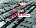
 
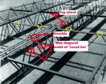
Point to where your green and red seperate elements would meet on this pic please......
vs180214-005.jpg
 
So, you agree that on the long span trusses, the steels running from perimeter to cores form the knuckles. Just not in that particular pic.

Right. I understand that you think that, yes.
You need to answer the issue at hand first gerrycan. You thought the knuckles we keep seeing were formed by the "bridging trusses" per this drawing with the yellow circles you added...
yellow studs.jpg

Isn't that correct gerrycan? Or do I need to get the exact quote? You changed you thinking to agree with me after you were shown you were wrong.
 
Yup, go get the quote, and also point to where your green and red element meet in the pic below please...
vs180214-005.jpg
 
The publication you are citing came out in 1964. The structural engineers were using a draft of the newly revised codes from 1968! How can you say that those drawings from the 1964 publication is what went out in the final, approved construction set? They don't even match what was actually seen!.

Glad to see that your opinion on the veracity of the 1964 publication has changed though.
 
Point to where your green and red separate elements would meet on this pic please......
:lamo

That's the whole point! YOU presented drawings from a 1964 publication and took them as what was actually installed. I am pointing out to you that those drawings are wrong and you can't use them because there AREN'T what was actually installed. Hence the separate elements I pointed out.

WHAT WAS INSTALLED DIDN'T HAVE SEPERATE ELEMENTS LIKE YOUR 1964 PUBLICATION INDICATES!

The trusses had "round bar" that bent at the top chord of the trusses and continued below to form the "web diagonals". My oh my are you confused.
 
Glad to see that your opinion on the veracity of the 1964 publication has changed though.
My opinion NEVER changed gerrycan. I have said from the start that what the drawings show is NOT what was installed.
 
Read the booklet again.

Edit - scrub the "again" from that
 
Right. I understand that you think that, yes.
It's fact gerrycan. It basic drawing and blueprint creation standard. This'll help you...

basic-blueprint-reading-15-638.jpg

basic-blueprint-reading-16-638.jpg
 
Read the booklet again.

Edit - scrub the "again" from that
My reading the booklet is not going to help you confusion on this matter.
 
You think that these are 2 seperate elements as per the 1964 booklet, and then Skilling had them change the design to make them one single element.
That is beyond dumb. But you're welcome to think it.
 
Sooooo...

Did you think the knuckles were from the "bridging truss" gerrycan? You messed up didn't you? Why yes you did!

I said they were formed by the open web trusses that were running at 90 degrees to the core -> perimeter direction.

Go get the quote you promised...

ADD - for some short spans I should have said
 
You think that these are 2 seperate elements as per the 1964 booklet,
Yes, and proven.

and then Skilling had them change the design to make them one single element.
That is beyond dumb. But you're welcome to think it.
Is it gerrycan?

Find me photos of any of the trusses that look like what is in the 1964 publication then WITH the non-round bar and separate elements. I'll wait.
 
I said they were formed by the open web trusses that were running at 90 degrees to the core -> perimeter direction.

Go get the quote you promised...

ADD - for some short spans I should have said

See post #72
 
Back
Top Bottom